
The commission for this project was from a driver who wanted an LED fitted to his motor vehicle that could flash briefly at regular intervals in the manner of a real car intruder alarm. This was to be powered from a PP3 battery rather than the main 12 volt system. The customer is always right.
The main problem needing to be adressed is battery life. Fortunately, the realistic duty cycle is low: about 300 ms on against two seconds off. OTOH, the PP3's 9 volt emf is far higher than the 1.8 volts (or thereabouts) for most red LEDs. If you use a series resistor to lower the drive then you are throwing away 80% of your power as heat.
The obvious solution is to use an inductive switching method to control the LED current. At first thought, a suitable choice of L would allow the current to ramp up to about 30 mA in a short space of time, and then ramp down again over 300 ms. Surprisingly, this inductance is around 18 henries. OK, that isn't an inconceivable size, but it's not readily available and would be bulky and expensive.
Second idea: there are hundreds of switch-mode power regulators that work at upwards of 50 kHz and so require far smaller inductors. Better yet, there are some advertised as 'LED current controllers'. Must be the way to go? Err, no. This last type is most often intended for high power white LEDs in room lighting with 110/230 volt AC feed. Even if their control loops can be stabilised to work at 30 mA, the efficiency is going to be poor.
Third idea: use a standard switching voltage regulator and modify it for current output. The snag is that the feedback input to these chips needs a voltage between about 1.2 and 2.5. if you use a series resistor to produce that signal then your efficiency is rubbish. OK, you might choose a smaller resistor and then an op-amp to amplify the signal, but that's not pleasant if you are trying to shave every μA off the budget. Remember that the amp is still sitting there eating power between flashes.
Idea number four: discrete switching circuit. The attraction of this is that you really aren't bothered about the accuracy of the current drive. Build something simple-stupid that isn't lumbered by overheads -
 TM1 can be adjusted to give the required light-up period, whilst R6 can
be altered to vary the repetition rate. With U1 pin 4 in the high
state, the current drive is off and the entire circuit consumes just a
couple of μA.
TM1 can be adjusted to give the required light-up period, whilst R6 can
be altered to vary the repetition rate. With U1 pin 4 in the high
state, the current drive is off and the entire circuit consumes just a
couple of μA.
With U1 pin 4 in the low state Q2 is turned on and supplies almost 9 volts to the gate of Q1. Q1 pulls the bottom end of L1 to ground. The top end of L1 falls no lower than battery volts less the drops due to the LED and R1. Once the current has ramped up to about 30 mA, the drop across R1 becomes sufficient to turn off Q2. When Q1 stops conducting the inductor goes into flyback mode, maintaining conduction through D1.
R4 supplies hysteresis to the system by helping to turn on Q2 as Q1 turns on. Conversely, only when the current falls below about 15 mA during flyback will the R1 volt drop allow Q2 to restart. This is elegant and it works. It is somewhat sensitive to battery volts, but that matters little because efficiency is still maintained.
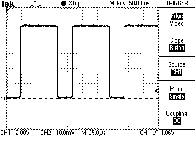
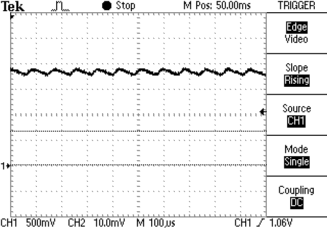
Current build-up lasts about 25 μs and flyback lasts 60 μs as shown in the screen shot. Other shots: the Q1 drain waveform and the LED drop.
Attempts to improve efficiency by using the LED itself in place of the flywheel diode must take into account that the reverse breakdown voltage of most LEDs is just 5 volts. Bother.
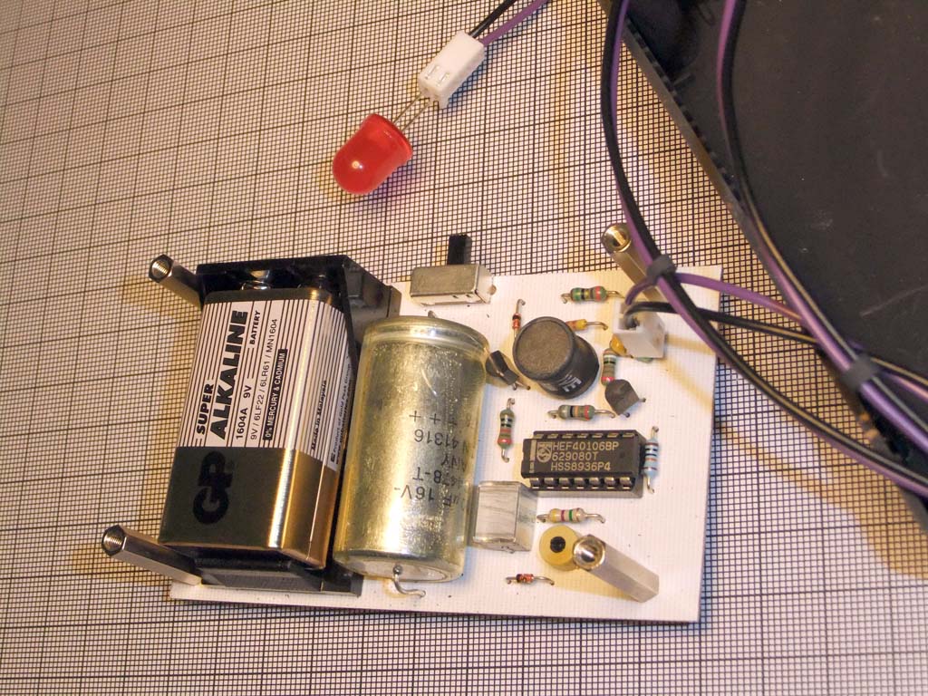


A standard ABS box was used to house the PCB, into which holes were cut
in the side for the power switch and output lead from PL1 to the LED. A
strip of velcro on the lid allows convenient mounting under the dash.
The prototype had insufficient space for PL1, so C6 was moved out the
way on the final board layout.
By careful selection of board dimensions and the length of the four
threaded pillars the assembly can be held snugly inside the box without
additional fixing screws.
Shorting C2 gives continuous current through the LED, so makes debugging simpler. Adjust TM1 for your prefered light-up period.
Does it work? Yes. Is it's efficiency good? Only about 60%. However, that's a huge improvement over the 20% that you'd get with resistive drop, but still disappointing. With a bit of faffing it might be possible to reduce the drop across the sense resistor a bit further.
Frankly, it might be better to use a CA3140 op-amp to do the sensing; but I'd need to regain the will to live first. The 4,700 μF supply decoupling is overkill intended to eek out longer life from a sagging battery. Replace with 100 μF to save space and cost.
Of course, now that this article has revealed the design, the entire idea is compromised. All any potential auto-thief needs is a photodiode mounted in a parabolic reflector pointed at the LED and an oscilloscope to display the 18 kHz switching waveform and he knows that the alarm is just a dummy. Dohhh!
This includes some order codes for Rapid Electronics.
| Part | Value | Device |
|---|---|---|
| B1 | 9V | Battery, PP3, RE18-2990 |
| C1 | 100n | Cap., ceramic, 63 V |
| C2 | 1u | Cap., polyester, 250 V |
| C3 | 4700u | Cap., Alumin., 16 V |
| C6 | 100n | Cap., ceramic, 63 V |
| D1 | BAT85 | Diode, Schottky |
| D2 | 1N4148 | Diode, Si |
| D3 | BAT85 | Diode, Schottky |
| FX1 | 3mm | Fixing hole, RE33-3560 |
| FX2 | 3mm | Fixing hole, RE33-3560 |
| FX3 | 3mm | Fixing hole, RE33-3560 |
| FX4 | 3mm | Fixing hole, RE33-3560 |
| L1 | 10mH | Inductor, RE88-1548 |
| PL1 | PL02 | Pin header, 1-row x 2-way |
| Q1 | VN10 | MOSFET, N-channel |
| Q2 | BC557 | Transistor, NPN signal |
| R1 | 15R | Resistor |
| R2 | 3k9 | Resistor |
| R3 | 10k | Resistor |
| R4 | 180k | Resistor |
| R5 | 100k | Resistor |
| R6 | 4M7 | Resistor |
| S1 | RE76-0271 | Switch, SPDT, slide |
| TM1 | 1M | Trim res., 1/4 in dia. |
| U1 | CD40106 | CMOS Schmitt inverter, hex |
[↑
Richard's Home Page]
[↑
Projects Page]
Feedback to: richard at clarcana.info
Last modified: 2012 April 30th.